01 - LED Experiment #1 (revised)
March 2026
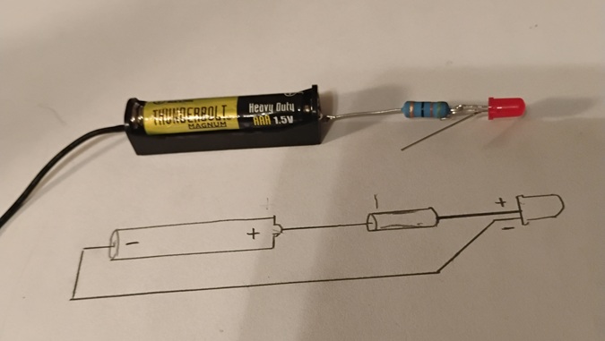
This is the first LED illumination experiment I've attempted. To light a simple .5mm LED using a 500 ohm resistor and two 1.5v batteries in series. Initially without a project enclosure, but still it works.
Testing Results*:
At this point, it was discovered that one of the two 1.5v in series batteries was completely dead (0.0v). The second maintained approximately 1.3v, leaving the total (of course) at 1.3v. Apparantly not enough to illuminate the LED. There for, it was decided to replace the one defective battery with a fully charged 1.5v battery (effectively 1.65v), and restart the test.
Test #2 Results*:
* Voltages displayed are after indicated testing hours, except for initial measurement.
** Strong initial illumination, but substantial degradation after first 15 minutes.
March 2026
This is the first LED illumination experiment I've attempted. To light a simple .5mm LED using a 500 ohm resistor and two 1.5v batteries in series. Initially without a project enclosure, but still it works.
Testing Results*:
| Exp #1-a | 0 hrs | 3.2v | |
| +3 hrs | 2.78v | ||
| +5 hrs | 1.34v | Dim illumination | |
| +3 hrs | 0.57v | No illumination | |
| Total hours | 11 | No illumination |
At this point, it was discovered that one of the two 1.5v in series batteries was completely dead (0.0v). The second maintained approximately 1.3v, leaving the total (of course) at 1.3v. Apparantly not enough to illuminate the LED. There for, it was decided to replace the one defective battery with a fully charged 1.5v battery (effectively 1.65v), and restart the test.
Test #2 Results*:
| Exp #1-b | 0 hrs | 3.2v | |
| +2 hrs | 1.4v | ** | |
| +5 hrs | 1.29v | No illumination | |
| +2 hrs | 1.25v | No illumination | |
| +5 hrs | 1.23v | No illumination | |
| Total hours | 14 |
* Voltages displayed are after indicated testing hours, except for initial measurement.
** Strong initial illumination, but substantial degradation after first 15 minutes.
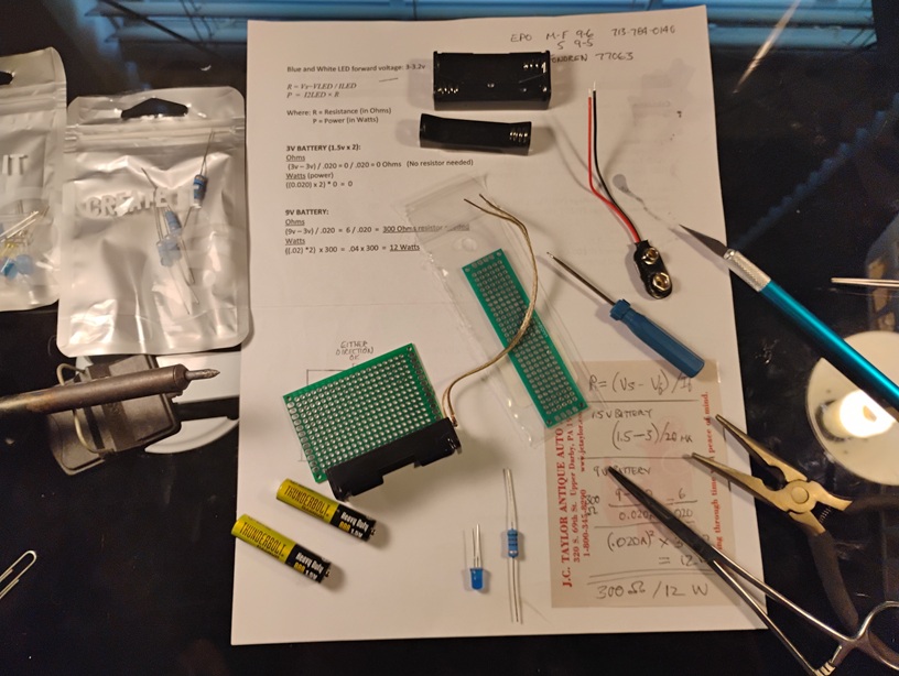
Building a basic LED activator
1st attempt
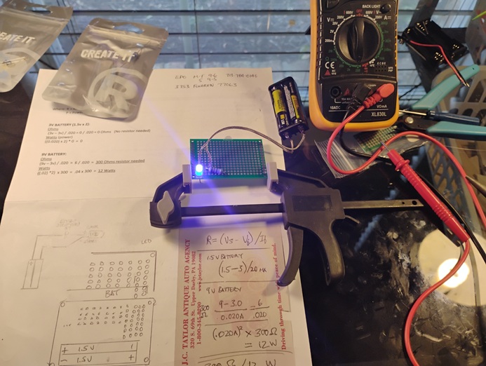
2nd attempt
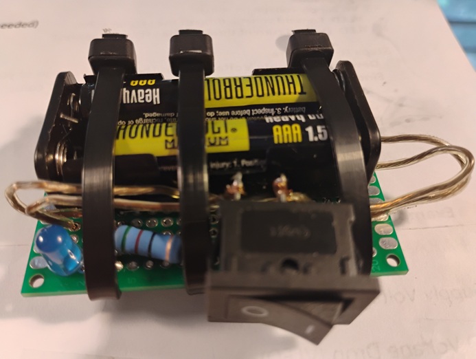
The finished activator
02 - LED Experiment #2
March 2026
My second attempt, using a .5mm LED, a 500 ohm resistor and one 1.5v battery (later modified to use one 9v battery).
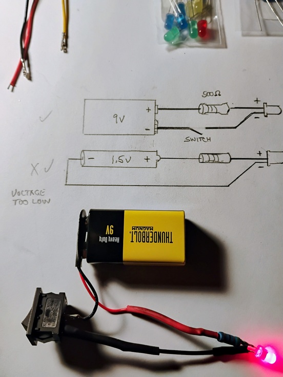
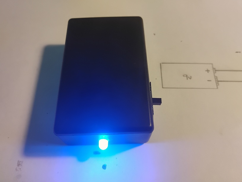
The LED did light up, but can be seen only in a dark environment (image 2), as the voltage (1.5v) was too low.
Altering the power source to 9v provided plenty enough power (image 3).
March 2026
My second attempt, using a .5mm LED, a 500 ohm resistor and one 1.5v battery (later modified to use one 9v battery).
The LED did light up, but can be seen only in a dark environment (image 2), as the voltage (1.5v) was too low.
Altering the power source to 9v provided plenty enough power (image 3).
 Experiment 02
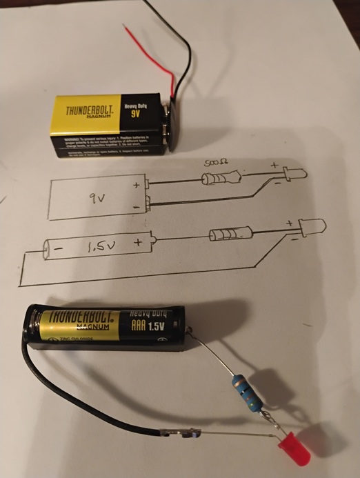
03 - LED Experiment #3
April 2026
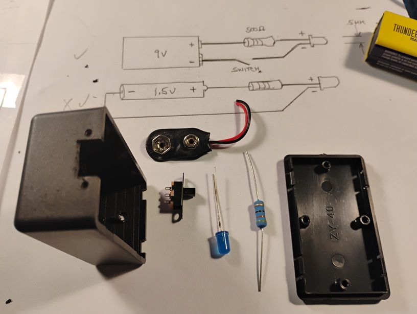
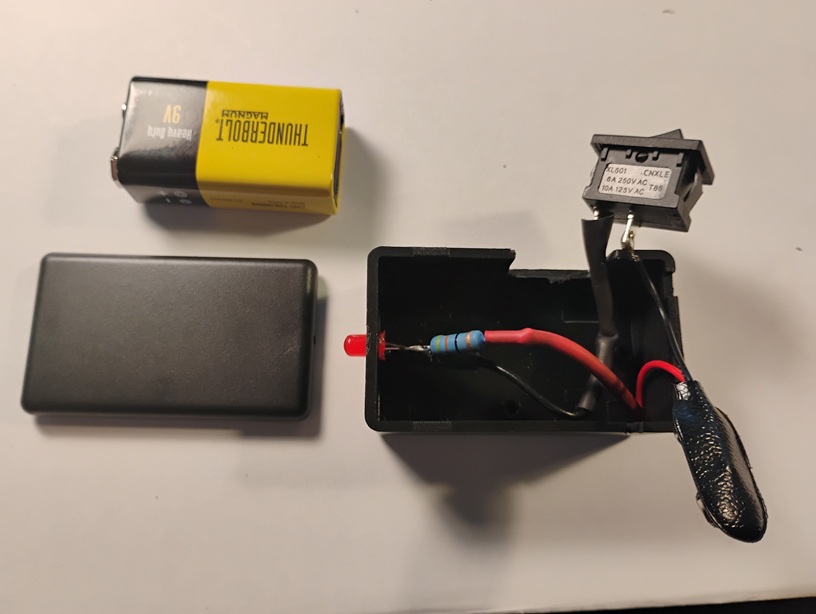
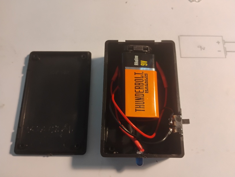
My third attempt. All components aquired (.5mm LED, 500 ohm resistor, switch, wire, solder, 9v battery and adapter, project enclosure).
Testing before mounting in the enclosure, the LED did light (image 2).
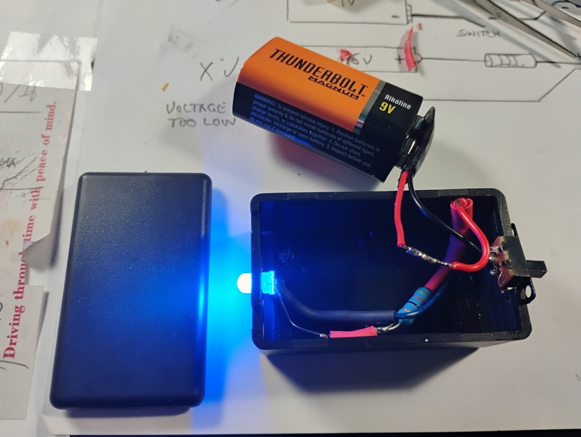
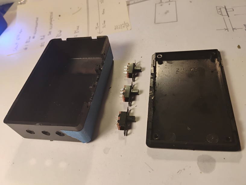
Testing with (some) components mounted in the enclosure (image 3). This revealed that when using a 9v battery as the power source, this particular enclosure is too small.
A too small enclosure forced mounting the power supply outside of the enclosure (image 4). Still, several modifications to the plastic enclosure were necessary, such as making a 1cm x 5mm void for mounting the switch, drilling a 3/16 hole for the actual LED, and tab reductions to the top closing piece (picture 3 above, left, the latter only for this experiment, future experiments should use a larger enclosure).
April 2026
My third attempt. All components aquired (.5mm LED, 500 ohm resistor, switch, wire, solder, 9v battery and adapter, project enclosure).
Testing before mounting in the enclosure, the LED did light (image 2).
Testing with (some) components mounted in the enclosure (image 3). This revealed that when using a 9v battery as the power source, this particular enclosure is too small.
A too small enclosure forced mounting the power supply outside of the enclosure (image 4). Still, several modifications to the plastic enclosure were necessary, such as making a 1cm x 5mm void for mounting the switch, drilling a 3/16 hole for the actual LED, and tab reductions to the top closing piece (picture 3 above, left, the latter only for this experiment, future experiments should use a larger enclosure).
 Experiment 03
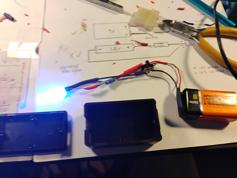
04 - LED Experiment #2 (revisited)
April 2026
The first attempt at the red LED was without having a project box (an enclosure). This second attempt is placing experiment #2 into a small enclosure. The stock enclosure is made out of plastic, and required a number of modifications.
* Voltages displayed are after indicated testing hours, except for initial measurement.
** For some unknown reason after a total of 11 hours, then a long rest, the 9v battery seemed to regain voltage.
***Again, after a long rest, the 9v battery seemed to regain voltage.
April 2026
The first attempt at the red LED was without having a project box (an enclosure). This second attempt is placing experiment #2 into a small enclosure. The stock enclosure is made out of plastic, and required a number of modifications.
- A 2cm X 1cm cutout was needed to accommodate the larger switch.
- A 3/16" hole needed to be drilled to accommodate the 5mm LED.
- A small access divot was needed to allow the positive and negative battery wires to exit the enclosure and connect to the battery.
| Exp #2 | 0 hrs | 9.67v | |
| +3 hrs | 8.72v | ||
| +5 hrs | 8.36v | ||
| +3 hrs | 6.54v | ||
| +3 hrs | 8.21v | ** | |
| +2 hrs | 7.66v | ||
| +5 hrs | 3.86v | Substantial illumination | |
| +2 hrs | 7.70v | Substantial illumination*** | |
| +5 hrs | 7.74v | Dim illumination | |
| +6 hrs | 6.82v | Dim illumination | |
| Total hours | 33 |
* Voltages displayed are after indicated testing hours, except for initial measurement.
** For some unknown reason after a total of 11 hours, then a long rest, the 9v battery seemed to regain voltage.
***Again, after a long rest, the 9v battery seemed to regain voltage.
05 - LED Experiment #3 (revisited)
April 2026
The second attempt at a blue LED (experiment #3) failed after what seemed to a short time of illumination. I'm guessing less than 1 hour. My first suspitions were that the LED drainted the 9v battery below 9 volts. It seemed that when voltage was measured (after the resistor), voltage dropped to 8.87v. This (seemingly) confirmed my suspicion. But that would not hold true. Removing the battery from the assembly, and re-checking voltage showed the battery above its 9v threshold, and thus, insufficiant voltage proved NOT to be the culprit.
Next, using a VOM, I checked for continuity, the wiring, the switch and all connection points, which all proved good with 0 Ohms. This left only the LED as the culprit.
Still, to prove the blue LED was bad, using aligator clips, I tested the entire circuit with a new blue LED, which illuminated perfectly. Thus, I cut out the bad LED, soldered in the known good blue LED, and reassembled the project. Now it's working again.
Testing Results*:
* Voltages displayed are after indicated testing hours, except for initial measurement.
April 2026
The second attempt at a blue LED (experiment #3) failed after what seemed to a short time of illumination. I'm guessing less than 1 hour. My first suspitions were that the LED drainted the 9v battery below 9 volts. It seemed that when voltage was measured (after the resistor), voltage dropped to 8.87v. This (seemingly) confirmed my suspicion. But that would not hold true. Removing the battery from the assembly, and re-checking voltage showed the battery above its 9v threshold, and thus, insufficiant voltage proved NOT to be the culprit.
Next, using a VOM, I checked for continuity, the wiring, the switch and all connection points, which all proved good with 0 Ohms. This left only the LED as the culprit.
Still, to prove the blue LED was bad, using aligator clips, I tested the entire circuit with a new blue LED, which illuminated perfectly. Thus, I cut out the bad LED, soldered in the known good blue LED, and reassembled the project. Now it's working again.
Testing Results*:
| Exp #3 | 0 hrs | 9.67v | |
| +3 hrs | 8.08v | ||
| +5 hrs | 6.85v | ||
| +3 hrs | 5.29v | ||
| +5 hrs | 6.24v | ||
| +2 hrs | 3.86v | Substantial voltage drop | |
| +5 hrs | 7.71v | Substantial illumination | |
| +2 hrs | 3.28v | Substantial illumination | |
| +5 hrs | 3.14v | Moderate illumination | |
| +6 hrs | 2.30v | Moderate illumination | |
| Total hours | 36 |
* Voltages displayed are after indicated testing hours, except for initial measurement.
06 - LED Experiment #4
April 2026.
This forth experiment is using an different resistor, in place of the old 500 ohm one. This is an attempt to allow the LED to draw less amperage from the power supply (the battery), which should allow the LED to remain illumniated for much longer.
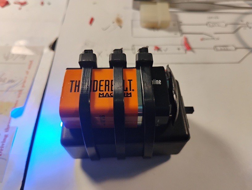
This experiment is also using a larger project box, finally allowing storage of the power supply to be stored inside of the encloser. With the battery stored inside, yet with little remaining space inside, inert padding material was necessary to prevent movement (rattling) of the battery. Testing Results*:
* Voltages displayed are after indicated testing hours, except for initial measurement.
April 2026.
This forth experiment is using an different resistor, in place of the old 500 ohm one. This is an attempt to allow the LED to draw less amperage from the power supply (the battery), which should allow the LED to remain illumniated for much longer.
This experiment is also using a larger project box, finally allowing storage of the power supply to be stored inside of the encloser. With the battery stored inside, yet with little remaining space inside, inert padding material was necessary to prevent movement (rattling) of the battery. Testing Results*:
| Exp #4 | 0 hrs | 9.67v | |
| +5 hrs | 8.59v | Full illumination | |
| +2 hrs | 8.49v | Full illumination | |
| +5 hrs | 8.33v | Full illumination | |
| +6 hrs | 7.99v | Good illumination | |
| Total hours | 18 |
* Voltages displayed are after indicated testing hours, except for initial measurement.
07 - LED Experiment #5
May 2026
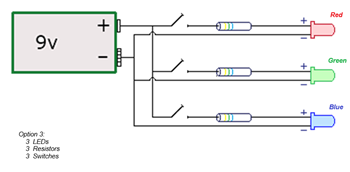
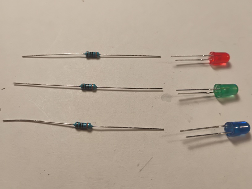
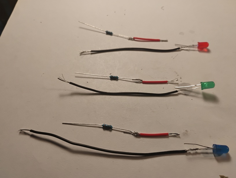
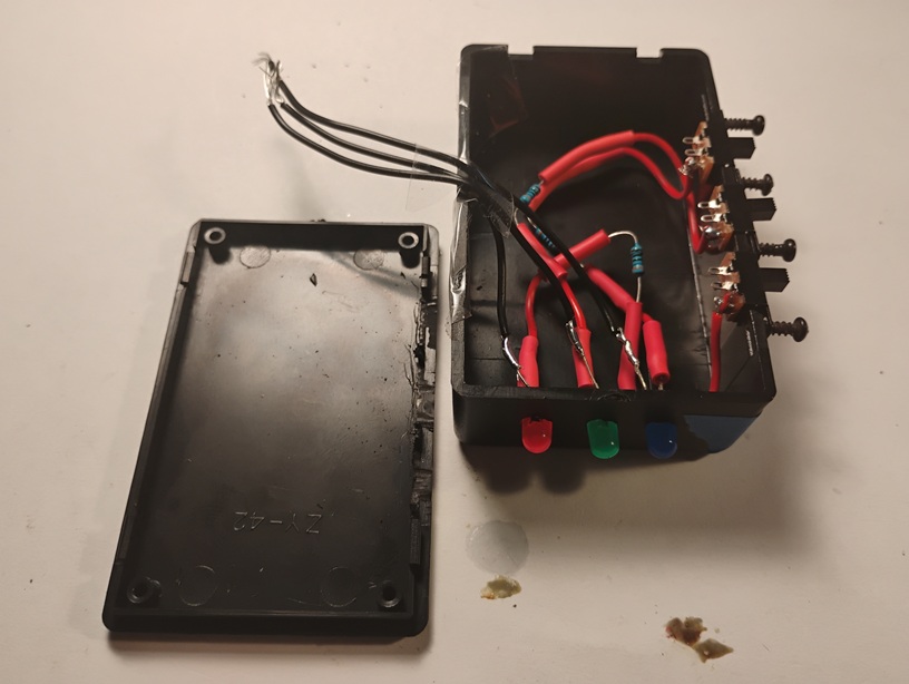
This fifth attempt is for multiple LEDs (three) in a single enclosure, still with the same single 9v power supply.
This is strictly a matter of convenience, so that if needed, the illuminated LED (red, green or blue) could be easily changed using a simple on/off switch, one for each of the three colors. Thus, three separte circuits were needed while still using a common power supply. As a side effect, this allows circuit design allows for all three colors to be illuminated at the same time. Unfortunately, this results is a substantially higher power draw on the battery, which will reduce its life sugnificantly.
A better circuit design would be something that would allow only one LET to be illuminated at a time.
Testing Results*:
* Voltages displayed are after indicated testing hours, except for initial measurement.
May 2026
This fifth attempt is for multiple LEDs (three) in a single enclosure, still with the same single 9v power supply.
This is strictly a matter of convenience, so that if needed, the illuminated LED (red, green or blue) could be easily changed using a simple on/off switch, one for each of the three colors. Thus, three separte circuits were needed while still using a common power supply. As a side effect, this allows circuit design allows for all three colors to be illuminated at the same time. Unfortunately, this results is a substantially higher power draw on the battery, which will reduce its life sugnificantly.
A better circuit design would be something that would allow only one LET to be illuminated at a time.

Testing Results*:
| Exp #5 | 0 hrs | 9.68v | |
| +6 hrs | 7.99v | ||
| Total hours | 6 |
* Voltages displayed are after indicated testing hours, except for initial measurement.
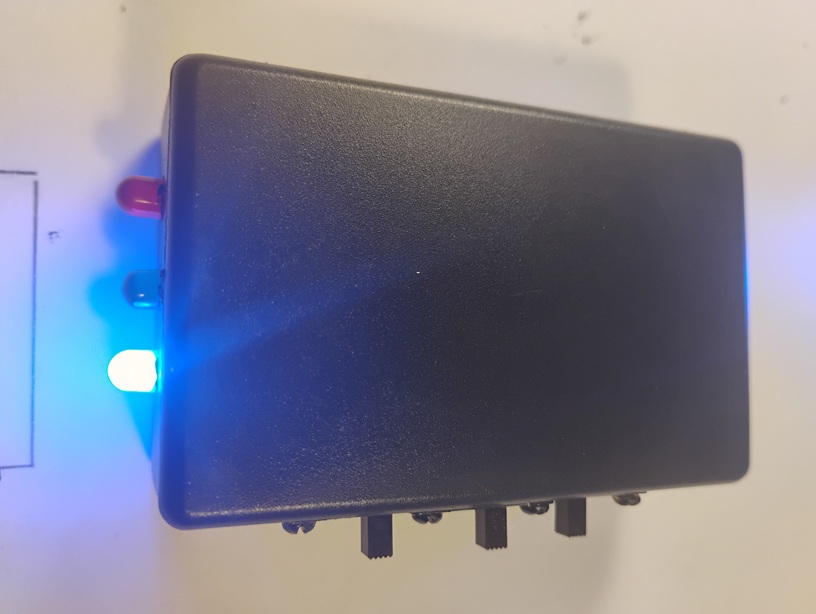
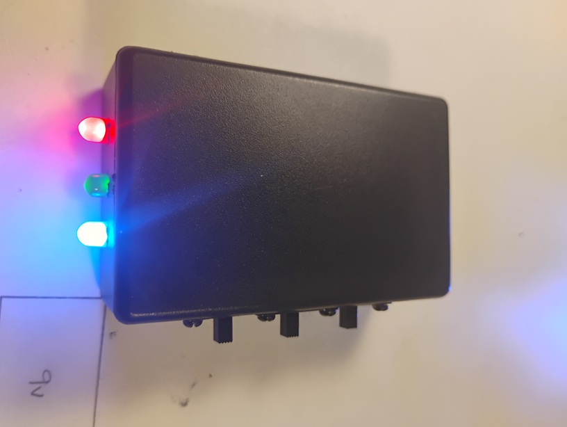
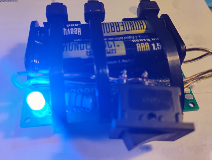
Showing all three LEDs illuminated